4. Magnetic Effects Of Current-Full
Q.1 Give a brief history of discovery of “magnetism”?
Ans. Discovery of Magnetism:- There are several early theories about the discovery of magnetism. According to one theory, more than two thousand years ago, a sphere boy, Magnes, was tending his flock of sheep on Mount Ida of the Island Crete. He had with him a long stick wit an iron point. As he stood watching his sheep, he rested his stick against a piece of stone. To his great surprise, he found the tip of his stick strongly attracted by the rock and he experienced some difficulty in removing it. He grew curious to know its cause. Upon digging the ground, he found a stone which has the peculiar property of attracting small pieces of iron towards it. As Magnes was the first to discover this magnetic rock, it was named after him as magnet.
According to another view, pieces of magnetic rocks were first discovered in the province of Magnesia in Asia Minor (Magnesia is the modern town of Manisa in western Turkey). After the name of the province, it was named ‘Magnetite’. The word magnet is derived from magnetite and the property of attracting small pieces of iron by magnet was called magnetism.
Q.2 Define:
I. Magnet II. Magnetism III. Bar Magnet
Ans. I. Magnet:- The substance which has both attractive (i.e. attracts pieces of iron, steel, nickel etc.) and directive properties is known as a magnet. It is also called a loadstone.
II. Magnetism:- The property of a magnet or a loadstone to attract iron fillings is called magnetism.
III. Bar Magnet:- A Bar magnet is a long rectangular or circular bar of uniform cross-section which attracts pieces of iron, steel etc. A magnet has two poles near its ends: North Pole (N) and South Pole (S).
Q.3 Define magnetic field. Give its Unit.
Ans. Magnetic Field:- The space around a magnet in which the force of attraction and repulsion due to the magnet can be detected is called the magnetic field.
The magnetic field has both magnitude as well as direction.
The S.I.Unit of magnetic field is Newton/Ampere-meter. It is also called Tesla and is denoted by T.
1T=1Newton1ampere x
1meter
ð1T=1 N/Am
The magnetic field (B)of earth near its surface = 0.3 x 10⁻⁴ T.
Q.4 What are magnetic field lines? What are the properties of magnetic field lines?
Ans. Magnetic Field Lines:- A magnetic field is described by drawing the magnetic field lines. When a magnet is placed on a cardboard sheet and gently some iron fillings are sprinkled uniformly in a pattern as shown in fig.
The iron fillings arranges themselves bcause of the fact that each piece of iron filling becomes a small magnet and experiences a force in a certain direction in the magnetic field are called ma gnetic field lines or magnetic lines of force.
Properties of Magnetic Field Lines:– Some properties of magnetic field lines are as:
(i). The magnetic field lines originate from the north pole of the magnet and ends at its south pole.
(ii). The magnetic field lines are crowded near the poles where the magnetic field is strong and are far apart near the middle of the magnet where the magnetic field is weak.
(iii). The magnetic field lines do not intersect one another, if they do so, there would be two directions of magnetic at that point, which is not possible.
(iv). If the field lines are parallel and equidistant, these represents a uniform magnetic field.
Q.5 Describe Oersted’s experiment to demonstrate the magnetic effect of current?
Ans. Oersted’s Experiment:– The magnetic effect of current was discovered by the Copenhagen Physics Professor Hans Christian Oersted in 1820. He found that a wire carrying a current was able to deflect a compass needle. Now, the compass needle is a tiny magnet which can be deflected only by a magnetic field. Since a current carrying wire was able to deflect a compass needle, it implies that a current flowing in a wire produces a magnetic field around it.
Verification:- Take a thick insulated copper wire AB whose ends are connected to a battery through a key (K) and fixed in the North-South direction. Put a plotting compass under the wire AB as shown in fig.
When no current is flowing in the wire AB, the compass needle is parallel to the wire AB and points in the usual north-south direction. But, on passing electric current through the wire AB, the compass needle is deflected from its north-south direction as shown in fig.2. and when the current is switched off, the compass needle returns back to its original position. On reversing the direction of current, the needle moves in the reverse direction.
The deflection of compass needle by the current carrying wire in the above experiment shows that an electric current produces a magnetic field around it.
Q.6 What is magnetic effect of current?
Ans. Magnetic Effect of Current:- When electric current is passed through a conductor, magnetic field is caused around it. This is known as magnetic effect of current. When the flow of current is stopped, magnetic field also disappears.
Q.7 Describe an experimental arrangement to demonstrate the formation of magnetic field pattern due to straight current-carrying conductor.
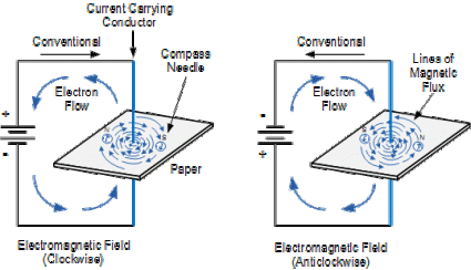
Ans. Magnetic Field Pattern Due to Straight Current Carrying Conductor:- The magnetic field lines around a straight conductor carrying current are concentric circles whose centres lie on the wire.
To demonstrate this, let us take a thick straight conductor (copper wire AB) and pass it through the centre ‘O’ of a thick cardboard. Connect the ends of the wire AB to the terminals of a battery through a key (K). also sprinkle some iron dust upon the cardboard. When current is passed through the wire AB and on tapping the cardboard gently, the iron dust is found to arrange itself in concentric circles around the wire. This clearly shows that a magnetic field has been set up due to the current flowing in the conductor.
To demonstrate the direction of the magnetic field around the conductor, let us place a small magnetic compass needle on the cardboard and observe the direction in which its north pole points. If the current is flowing in the wire upwards, the north-pole of the needle is seen to point in the anti-clockwise direction and vice-versa.
It has been found by experiments that the magnitude of magnetic field (B) is:
(i) directly proportional to the current (I) passing in the wire.
i.e B α I ①
& (ii) inversely proportional to the distance (r) from the wire.
i.e. B α 1r ②
From ① and ②, we get
B α Ir
Q.8 State and explain Maxwell’s right hand thumb rule.
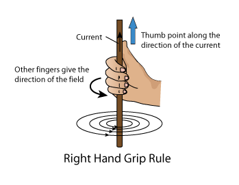
Ans. Maxwell’s Right-Hand Thumb Rule:- If the direction of current is known, then the direction of magnetic field produced by a straight wire carrying current can be obtained by using Maxwell’s Right-hand thumb rule.
According to Maxwell’s right-hand thumb rule,” Imagine that you are holding the current carrying wire in your right hand so that your thumb points in the direction of current, then the direction in which your fingers encircle the wire will give the direction of magnetic field lines around the wire.” E.g. If AB is a current carrying straight wire in which the direction of current is from A to B, is held in right hand such that the thumb points in the direction of current, then according to Maxwell’s right-hand thumb rule, the direction of curling fingers gives the direction of magnetic field lines(which is anti-clockwise here) as shown in fig.
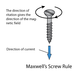
Maxwell’s right-hand thumb rule is also known as Maxwell’s Cork-screw rule according to which, “ Imagine driving a cork-screw in the direction of current, then the direction in which we turn its handle is the direction of magnetic field (or magnetic field lines).
Q.9 Describe the magnetic field pattern produced by a current carrying circular loop.
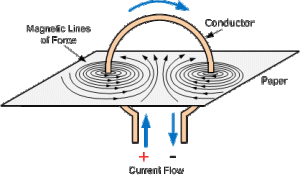
Ans. Magnetic field due to a current carrying circular loop (Wire):- To find the magnetic field due to a circular loop, it is held in a vertical plane and is made to pass through smooth cardboard in such a way that the centre (O) of the coil lies at the cardboard. When a current is passed through the coil and iron fillings are sprinkled on the cardboard. These iron fillings arrange themselves in a pattern as shown in fig.
The magnetic field lines near the coil are circular and concentric and becomes straight at the centre of the loop. By applying Maxwell’s right-hand thumb rule, it can be seen that each segment of circular wire carrying current produces magnetic field lines in the same direction within the loop and at the centre of the loop, all magnetic field lines are in the same direction and aid each other, due to which the strength of the magnetic field increases.
The magnitude of the magnetic field (B) at the of the coil is:
(i). directly proportional to the current (I) flowing it.
i.e. B α I ①
(ii). Inversely proportional to the radius (r) of the coil
i.e. B α 1r ②
(iii). directly proportional to total number of turns (N) in the coil.
i.e. B α N ③
From ①, ② and ③, we get
B
α I x Nr
A current carrying circular loop behaves as a thin magnet whose one face is a north pole and the other pole is a south pole.
Q.10 Describe the magnetic field pattern produced due to a current-carrying solenoid.
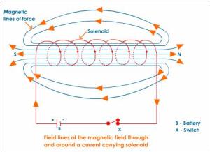
Ans. Magnetic field pattern due to a solenoid:- An insulated copper wire wound on a cylindrical cardboard (or plastic) tube such that its length is greater than its diameter is known as a solenoid.
To obtain the pattern of magnetic field due to a solenoid, consider a solenoid AB whose ends are connected to battery (B) through a key (K) as shown in fig.
When an electric current is passed through the solenoid (AB), it produces a magnetic field around it. The magnetic field produced by a solenoid is similar to that of a bar magnet. The magnetic field lines inside the solenoid are nearly straight and parallel to its axis and thus the magnetic field inside a solenoid is uniform. One end of the current carrying solenoid acts as a north pole and the other end acts as a south pole. The end of the solenoid which is attracted by the north pole of a bar magnet is called south pole while as that repelled by the north pole of the bar magnet is called the north pole of the solenoid.
The magnitude of the magnetic field (B) inside the solenoid is:
(i). directly proportional to the to the current flowing through it.
i.e. B α I ①
(ii). directly proportional to the number of turns per unit length of the solenoid(n).
i.e. B α n ②
From ① and ②, we get
B α nI
Where n = N/l.
Here, N = Total number of turns in the solenoid
And l = Length of solenoid.
Q.11 Discuss what happens when a current-carrying conductor is placed in a magnetic field.
OR
Explain the cause of force acting on a current-carrying conductor in a magnetic field.
Ans. Force on a current-carrying conductor placed in a magnetic field:- When a current-carrying conductor is placed in a magnetic field, it experiences a force, except when it is placed parallel to the magnetic field. In other words, when a current-carrying conductor is placed in a magnetic field, a mechanical force is exerted on the conductor which makes the conductor to move.
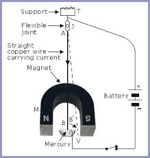
Experiment to demonstrate the force acting on a current carrying conductor in a magnetic field: The Kicking Wire Experiment:- A thick copper wire AB is suspended vertically from a support ‘T’ by means of a flexible joint ‘J’. the lower end B of this wire is dipped in a pool of mercury kept in a vessel and is free to move between the poles of a U-shaped magnet. An electric current is provided by connecting the end A of the wire with positive terminal of the battery and by dipping another wire from negative terminal into mercury pool as shown in fig.
Observations:- The following observations are made:
(i). When the key (K) is pressed, the current flows downwards and the wire AB is kicked forwards (as shown by AB’). This causes the wire to leave contact with the mercury and breaks the circuit. When the wire falls back to its original position, it reconnects with mercury and the action is repeated again and again.
(ii). on reversing the battery connections, the current in the wire flows upwards and the wire swings backwards out of mercury.
(iii). the direction of force on the wire is also reversed if the direction of magnetic field is reversed i.e. by turning the magnet so that its poles are reversed.
(iv). No force acts on a wire when it is parallel to the magnetic field.
Magnitude of Force:– It has been found experimentally that the force (F) is:
(i). directly proportional to the current (I).
i.e. F∝I ①
(ii). directly proportional to the length of the conductor inside the magnetic field.
i.e. F ∝l ②
(iii). directly proportional to the magnitude of the magnetic field.
i.e. F α B ③
From ①, ② and ③, we get
F∝I
l B
Or F=KxIxlxB
Where K = 1 is a constant of proportionality.
.: F=IxlxB
Q.12 State Fleming’s left-hand rule for the direction of force.
Ans. Fleming’s Left-hand Rule:- Fleming gave a simple rule to determine the direction of force acting on a current-carrying wire placed in a magnetic field. According to Fleming’s left-hand rule, “Stretch the forefinger, the central finger and the thumb of your left hand mutually perpendicular to each other. If the forefinger shows the direction of the magnetic field and the central finger shows the direction of current, then the thumb points in the direction of force (motion) on the conductor”
Q.14 State Fleming’s Right-hand rule.
Ans. Fleming’s right-hand Rule:- According to Fleming’s right-hand rule, “Stretch the forefinger, the central finger and the thumb of your right hand mutually perpendicular to each other. If the forefinger shows the direction of the magnetic field, the thumb shows the direction of motion (or force) of the conductor, then the central finger will indicate the direction of current in the conductor.
Q.14 Describe the principle, construction and working of electric motor.
Ans. Electric Motor:- An electric motor is a device which converts electrical energy into mechanical energy. A common electric motor works on direct current, so it is also known as D.C motor. Electric motor is used in electric fans, washing machines, refrigerators etc.
Principle:- A motor works on the principle that when rectangular coil carrying current is placed in magnetic field, a force acts on the coil which rotates it continuously.
Construction and working of Motor (D.C motor):- An electric motor (D.C. motor) consists of a reactangular coil frame ABCD. It is called armature. The armature can freely rotate about a spindle or shaft in the space between the two poles N and S of a horse-shoe type permanent magnet M. The two ends of the coil ABCD are welded permanently to the two half rings S1 and S2 which acts as a commutator. The function of a commutator ring is to reverse the direction of current flowing through the coil after every half rotation of the coil. Two carbon brushes P and Q are made to slightly pressed against the two half rings by means of springs and are joined to a battery (B), rheostat (Rh) and a switch (K).
When an electric current is passed through the coil ABCD, the magnetic field pushes the side CD down and AB up (according to left-hand rule). This means the coil rotates clock-wise. At half rotation, the polarity of the commutator changes since now it is S1 which contacts the brush P and S2 contacts with Q. this reversal pushes AB down and CD. In this way, a continues rotator motion is produced and electric motor is obtained.
Q.15 Define electromagnetic induction.
Ans. Electromagnetic Induction:- The phenomenon of production of electricity from magnetism is known as electromagnetic induction.
e.g. When a straight wire is moved up and down rapidly between the two poles of a horse shoe magnet, then electric current is placed in the wire.
Q. 16 What is an electric fuse? What is its importance?
Ans. Electric Fuse:– A fuse is a safety device having a short length of a thin wire made of tin-lead alloy (75% of lead and 25% of tin) having low melting point (near 200C0), which melts and breaks the circuit if the current exceeds a safe value.
An electric fuse works on the heating effect of current and is connected in series in the electric circuits.
An electric fuse is a very important device as it prevents damage to various electrical appliances in the house due to excessive current flowing through them.
Q.17 Define: (a). Alternating Current (A.C) (b). Direct Current (D.C)
Ans. (a). Alternating Current (A.C):- An electric current which changes its direction (i.e. polarity) after equal intervals of time is called alternating current.
In India, the frequency of A.C is 50 Hz.
(b). Direct Current (D.C):- An electric current which always flows in the same direction is called direct current. The polarities (+ve and -ve) of d.c. are fixed. E.g. The current supplied by a cell or battery is D.C.
A.C current D.C current
Q.18 What is an electromagnet? Give its uses.
Ans. Electromagnet:- An electric current can be used for making temporary magnets known as electromagnets. An electromagnet is a temporary strong magnet and consists of a long coil of insulated copper wire wound on a soft iron core.
To make an electromagnet, take a rod AB of soft iron and wind a coil of insulated copper wire around it. When an electric current is passed by connecting both the ends of copper wire to a battery, an electromagnet is formed.
The strength of electromagnet depends on:
(i). The number of turns of coil. The strength of an electromagnet increases on increasing the number of turns in the coil.
(ii). The current flowing in the coil. The strength of an electromagnet increases, if the current in the coil is increased.
Uses of Electromagnets:-
1. These are used in electrical devices like an electric bell, an electric fan, an electric motor or generator etc.
2. For lifting and transporting large masses of iron in the form of girders.
3. In medical practices for removing pieces of iron from wounds.
Q.19 What is a permanent magnet? Give its uses.
Ans. Permanent Magnet:- A permanent magnet is made from steel. As steel has more resistivity than iron, it does not lose its magnetism easily.
To make a permanent magnet, a steel bar is placed inside a solenoid and current is switched on and off several times, but not for a long time. On removing and testing the bar, it is found to be magnetized (i.e. formed a permanent magnet.)
Permanent magnets are usually made of alloys such as carbon steel, chromium steel, cobalt steel and alnico (Al, Ni, Co & Fe).
Uses: Permanent magnets are used in:
1. electric meters such as galvanometers, voltmeters, ammeters, speedometers etc.
2. micro-phones and loud-speakers
3. electric clocks.
Q.20 Distinguish between electromagnet and permanent magnet.
Ans.
|
Electromagnet |
Permanent Magnet |
|
1. An electromagnet is a temporary magnet as its magnetism is for the duration of current passing through it.
2. It can produce a very strong magnetic force.
3. The strength of an electromagnet can be changed by changing the number of turns in its coil or changing the current.
4. Its polarity can be changed by changing the direction of current in its coil. |
1. The bar magnet is a permanent magnet.
2. It produces a weak force of attraction.
3. The strength of a permanent magnet can not be changed.
4. Its polarity is fixed and can not be changed. |
Q.21 What is meant by:
(a). Short-Circuiting (b). Overloading
Ans.(a). Short-Circuiting:– when the plastic insulation of the live wire and the neutral wire gets torn, then the two wires touch each other. This touching of the live wire and neutral wire directly is known as short-circuit.
Short-circuiting occurs due to:
(i). damage to the insulation of power lines.
(ii). a fault in electric appliance due to which current do not pass through it.
(b). Overloading:- The current in a circuit depends upon the rating of the appliances connected to it. The choice of wires depends upon the maximum current estimated to pass through them. If the total power rating of the appliance exceeds this permitted limit, they tend to draw a large current. This is known as overloading.
Q.22 What is meant by “Earthing”? Why is it done?
Ans. Earthing:- Earthing means to connect the metal case of electrical appliance to the earth (zero potential) by means of a metal wire called earth wire.
Earthing is done to avoid the risk of electric shocks and thus helps to save ourselves.
Q.23 Advantages of parallel wiring…………… See answer in “Electricity”
Q.24. Disadvantages of series wiring ………… See answer in “Electricity”
……………………………………………………………………………………………
NOTES ARE ALSO AVALAIBLE ONLINE……………..
Visit:………………..
www.shaikhjaveed.wordpress.com
Facebook Page of R.P.H.S. Pulwama…….administrated by me…………
www.facebook.com/RadiantPublicHighSchoolPulwama
……………………………………………………………………………………………………………………..
